Local symmetry: Difference between revisions
mNo edit summary |
mNo edit summary |
||
| Line 53: | Line 53: | ||
Each mask must superimpose with the local region on the original density map when the mask and the map are centred at the same coordinates. The end of section 1 introduces such checks using UCSF Chimera. Once all the masks are ready, a STAR file ‘init_masklist.star’ with all the mask filenames should be generated manually, with the ith set of related regions marked using positive integer IDs. The STAR file below specifies ‘Trimer_mask1/2/3.mrc’ as the masks for all monomers in the trimer (ID = 1), and ‘Tetramer_mask1/2/3/4.mrc’ as the masks for all monomers in the tetramer (ID = 2). | Each mask must superimpose with the local region on the original density map when the mask and the map are centred at the same coordinates. The end of section 1 introduces such checks using UCSF Chimera. Once all the masks are ready, a STAR file ‘init_masklist.star’ with all the mask filenames should be generated manually, with the ith set of related regions marked using positive integer IDs. The STAR file below specifies ‘Trimer_mask1/2/3.mrc’ as the masks for all monomers in the trimer (ID = 1), and ‘Tetramer_mask1/2/3/4.mrc’ as the masks for all monomers in the tetramer (ID = 2). | ||
data_ | data_ | ||
loop_ | loop_ | ||
_rlnMaskName #1 | _rlnMaskName #1 | ||
_rlnAreaId #2 | _rlnAreaId #2 | ||
Trimer_mask1.mrc 1 | Trimer_mask1.mrc 1 | ||
Trimer_mask2.mrc 1 | Trimer_mask2.mrc 1 | ||
Trimer_mask3.mrc 1 | Trimer_mask3.mrc 1 | ||
Tetramer_mask1.mrc 2 | Tetramer_mask1.mrc 2 | ||
Tetramer_mask2.mrc 2 | Tetramer_mask2.mrc 2 | ||
Tetramer_mask3.mrc 2 | Tetramer_mask3.mrc 2 | ||
Tetramer_mask4.mrc 2 | Tetramer_mask4.mrc 2 | ||
Revision as of 02:46, 3 November 2017
TODO Shaoda
Definition of local symmetry in RELION

Local symmetry in RELION is implemented to average identical regions which cannot be simply related by overall symmetry (e.g. point group or helical) in cryo-EM density maps. Numbers of sets (N, N>=1) and identical regions (Ki, 1<=i<=N, Ki>=2) within each set can be arbitrary. The identical regions might be assembled into the whole structure, or they might only contribute to parts of densities which bind to other asymmetrical subunits.
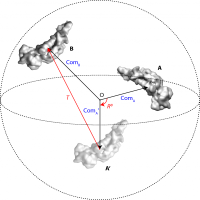
For each set of identical regions related by local symmetry, one soft-edged binary mask (Mi) is needed, covering any one of the asymmetrical subunits of the local symmetry. All the other regions are assumed to be identical in densities and their positions and orientations relative to the masked region are defined by local symmetry operators. Figure 1 shows a schematic example of a pseudo-dimer AB (N=1, K1=2) and the mask M1 covers the subunit A.
A transformation operator contains 6 parameters, 3 rotations φ, θ, ψ (following the definition of Euler angles in RELION) in degrees and 3 translations Δx, Δy, Δz in Angstroms. The pair of identical pieces of densities, A and B in Figure 1, corresponds to a unique operator Op = [φ, θ, ψ, Δx, Δy, Δz], which firstly rotates the masked region A to A’ around the centre O of the 3D particle box, and then translates the rotated densities A’ to fit onto the symmetry-related region B. The transformations are performed in real-space using trilinear interpolations. Note that all the symmetry-related regions must be located within the maximum sphere (dashed circle in Figure 1) inside the 3D particle box (D×D×D, in pixels) to avoid any loss of information during image transformations.
In order to impose local symmetry on a density map with N sets of identical regions, one mask is required for each set, which results in N masks in total. If the ith set contains of Ki (Ki>=2) identical regions, Ki – 1 operators needs to be defined. For example, two masks (Mtri, Mtetra) are required for a complex that consists of a trimer of one protein that is bound to a tetramer of another protein. Mtri covers a monomer of the trimer (along with 2 operators) and Mtetra covers a monomer of the tetramer (along with 3 operators).
The mask should be in MRC format and of the same dimensions in pixels as the 3D density map. The position of a mask must correspond to the position of the subunit of the density map in its 3D data array. For example, assume that a density map with the size of 300X300X300 pixels contains the pseudo-dimer AB in figure 1. The x, y, z integer subscripts of the 3D map range from -150 to +149. The subunit A is written into positions with x, y, z subscripts of +50 ~ +100 (approx.) in the 3D data array. Therefore, the soft-edged binary mask of A must be of 300X300X300 pixels in dimensions, and the (0, 1] mask values must be written into x, y, z subscripts of +50 ~ +100 (approx.). It should be taken care of because a mask of another definition writes (0, 1] values always around the centre of the box, i.e. for this case in subscripts of -25 ~ +25, and shifts of +75 are specified in the MRC header to show its relative position with respect to the density map. Such masks must be converted so that they conform to the definition here for local symmetry imposition. UCSF Chimera may be used to check a mask against the density map. []. If not, resample the mask on top of the density map (UCSF Chimera internal command ‘vop resample #2 onGrid #1’) and save the resampled mask. In a word, both the subunit densities and the mask values should be written to their absolute positions in the 3D data arrays in order to analyse the local symmetry.
[Figure 2] [Check a mask against the density map in UCSF Chimera.]
Given a density map and all the required masks, all the operators are written into a single STAR format file, with each entry consists of a mask file name and a 6-parameter operator.
Local symmetry operators for microtubules with seams
$$$ Example: 3-start 13-microtubule with seam $$$
Local symmetry STAR file (12 operators): ftp://ftp.mrc-lmb.cam.ac.uk/pub/she/localsym/localsym-3s13m.star
The only mask (binary, soft-edged, pixel size = 1.38 Angtroms): ftp://ftp.mrc-lmb.cam.ac.uk/pub/she/localsym/mask-7.mrc
The referential density map (pixel size = 1.38 Angstroms): ftp://ftp.mrc-lmb.cam.ac.uk/pub/she/localsym/ref-fil30.mrc
Although the map here has been low-pass filtered to 30 Angstroms (unpublished results from another group), it is recommended to use the best map you have to set up the local symmetry. Always display the referential map and the mask(s) simultaneously in UCSF Chimera for a check after you have constructed the mask(s).
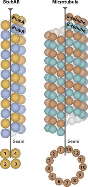
Note: Assume that as seen in the top-view/bottom-view, the proto-filaments are numbered as #1~#13 clockwise/counter-clockwise. The proto-filaments closest to the seam are #1 and #13 while the one opposite to the seam is numbered as #7. The only mask covers the tubulins (central ~50% of the box) along the proto-filament #7. The helical symmetry is defined along each proto-filament: twist = +0.1 degrees, rise = 83.1 Angstroms (with each pair of ab-tubulins treated as a subunit, or the building block of each proto-filament). In the local symmetry STAR file, the rot (or psi) angles are N*360/13 = N*27.69 degrees and the z translations are N*83.1*1.5/13 = N*9.59 Angstroms (N=-6~+6, without 0). All the other angles and translations are set to 0. The 12 operators (entries, each consisting of a rot angle and a z translation here) show how to move the whole proto-filament #7 onto any of the other 12 by a rotation around the helical axis and a translation along the axis.
It doesn't matter if you don't have a microtubule with seam as the starting reference. Given a referential 3-start 13-microtubule WITHOUT seam, you can just treat any proto-filament as #7 and the above mask and operators remain the same. The seam should become discernible after 3D auto-refinement if the local symmetry settings are correct.
Enable the local symmetry option for such structure: Copy the referential density map, the mask and the local symmetry STAR file to the project directory. Add '--local_symmetry localsym-3s13m.star --tau_fudge 13' as the additional option in 3D auto-refinement. We are still testing how '--tau_fudge' influences the 3D reconstructions with local symmetry. Unreasonably large values lead to over-fitting but the subsequent post-processing step will always give you a fair resolution estimate.
Searching for arbitrary local symmetry operators
List of masks
This section introduces a general approach of finding local symmetry operators for single-particle reconstructions. It requires the density map and the masks of all regions of interest as input (all in MRC format). An example structure consisting of a trimer bound to a tetramer (N=2, K1=3, K2=4) is used as an example. A total of 3+4=7 masks are required to mark all the regions of interest for calculating the operators, although only 2 masks (Mtri, Mtetra) are necessary in applying the symmetry after the operators are determined.
The density map and the masks converted from PDB models might lead to more accurate and stable operators. The same PDB model should be fitted to every set of identical regions and converted into MRC density maps of those local regions. Given an MRC density map, the standalone program ‘relion_mask_create’ writes out a soft-edged, binary mask:
relion_mask_create –-i Trimer_pdb1.mrc -–ini_threshold 0.01 –-extend_inimask 0 -–width_soft_edge 3 –-o Trimer_mask1.mrc
However, if the PDB structures are not readily available, a reconstruction result (e.g. from 3D reconstructions or post-processing) can be used as the input density map from which the masks are also generated.
Each mask must superimpose with the local region on the original density map when the mask and the map are centred at the same coordinates. The end of section 1 introduces such checks using UCSF Chimera. Once all the masks are ready, a STAR file ‘init_masklist.star’ with all the mask filenames should be generated manually, with the ith set of related regions marked using positive integer IDs. The STAR file below specifies ‘Trimer_mask1/2/3.mrc’ as the masks for all monomers in the trimer (ID = 1), and ‘Tetramer_mask1/2/3/4.mrc’ as the masks for all monomers in the tetramer (ID = 2).
data_
loop_
_rlnMaskName #1
_rlnAreaId #2
Trimer_mask1.mrc 1
Trimer_mask2.mrc 1
Trimer_mask3.mrc 1
Tetramer_mask1.mrc 2
Tetramer_mask2.mrc 2
Tetramer_mask3.mrc 2
Tetramer_mask4.mrc 2
